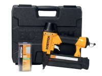
Here are some photos and information I compiled while stripping and
repairing my Bostitch BT200.
I didn't find this information anywhere else, which is surprising since I
own 6 of these and have found them to be somewhat prone to the diaphragm blowing out of its seating,
and breakage of the firing pin.
NOTE: when the gun will not fire a nail, but instead releases pressure
around the trigger area, chances are the diaphragm has become unseated
or was incorrectly installed. See disassembling and
reassembling frame cap below.
NOTE 2: This information is provided only to show you how I disassemble
and reassemble my own tools. This is not intended to encourage any such
behavior on your part. Any repair or modification to power tools
can be dangerous to your health.
Replacement parts can be found online.
(Good luck, though, with the Bostitch online store. When I ordered,
their website showed inventory for the parts, and charged my credit
card, promising delivery in a few days. Weeks later I called to find
out that only a few parts had been shipped - to the wrong address - and the
rest were backordered with no estimate of when they would be in-stock.
They had no problem with charging my credit card for all the items
despite having no idea when they would be getting the parts in.)
|
disassembling firing pin guide
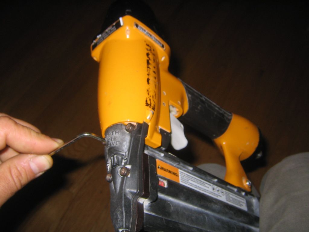
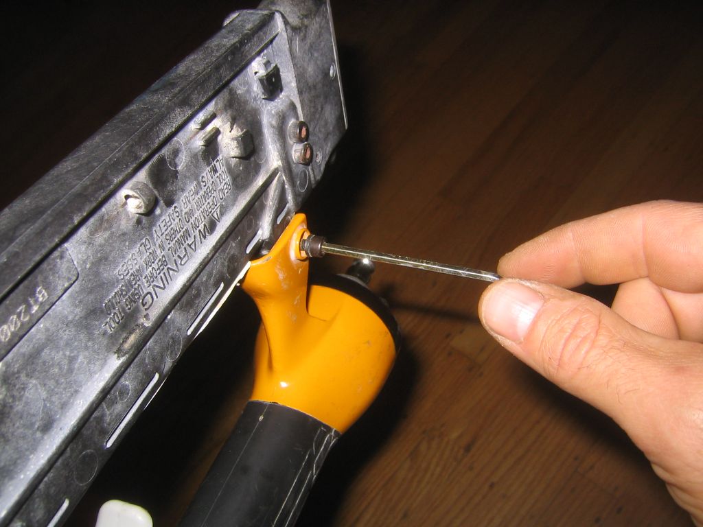
- undo the upper two bolts on the black faceplate (aka the trip cover) on the front of the gun (fig 1)
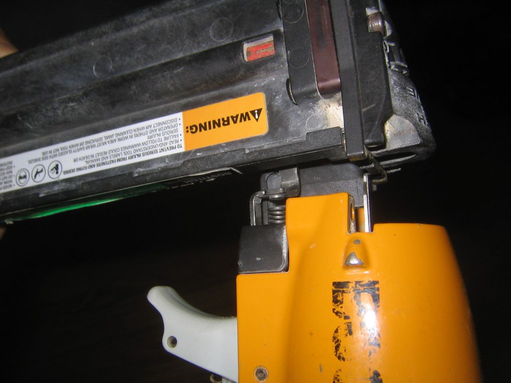
- undo bolt at rear of nail cartridge (fig 2)
- drop cartridge off of body
- undo remaining two bolts on front of cartridge
- pull everything apart and clean it
- use appropriate grease on parts before reassembly
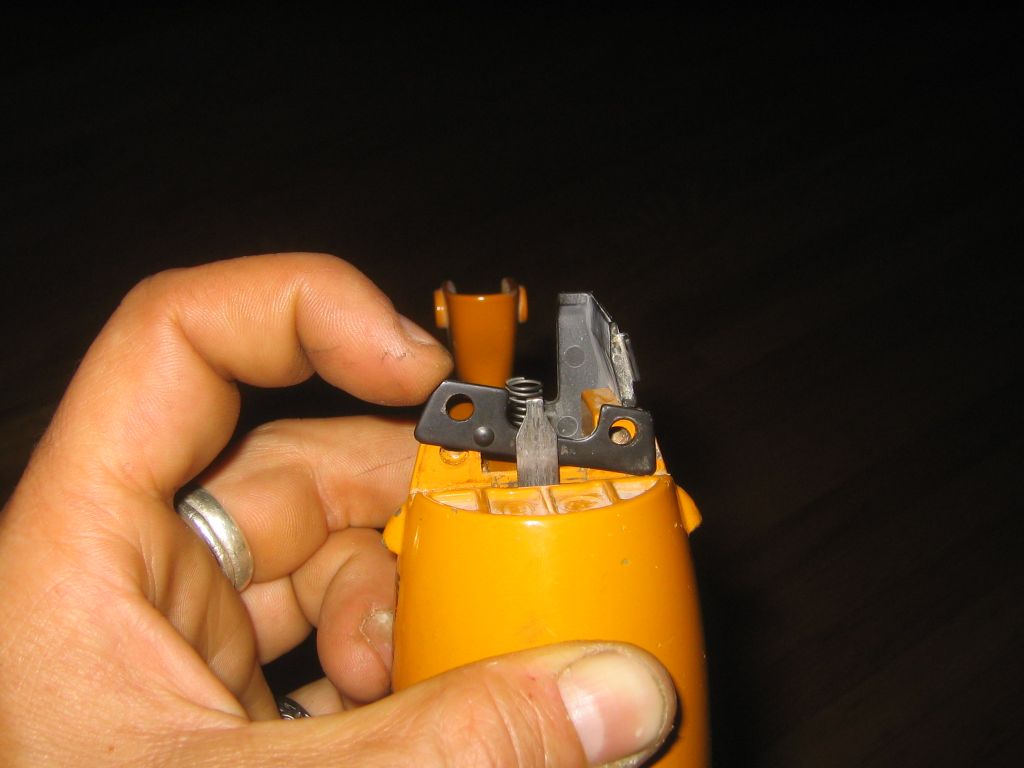
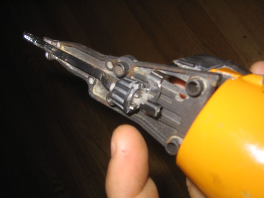
reassembling firing pin guide
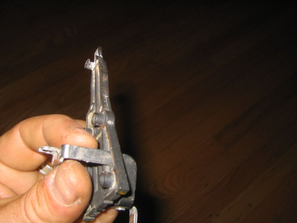
- thread the triangular firing pin backer plate (nose)
onto stainless steel
arm (upper trip) as shown (fig
3)
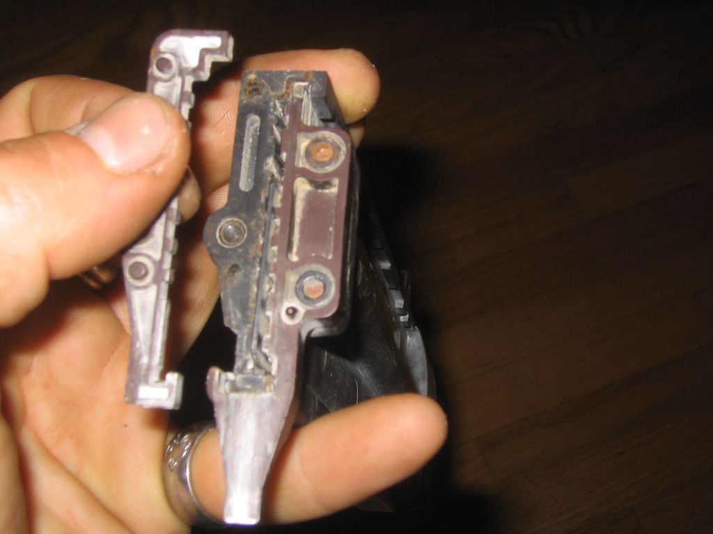
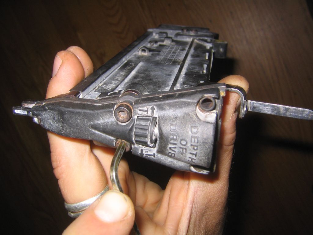
- place the rectangular safety trip rod (lower arm assembly)
under guide hook on nose (the hook can barely be seen in the upper left of fig 4)
- put fork of the stainless steel upper trip around
lower arm assembly, just above the thumbweel adjuster head (fig 4)
- place the faceplate (trip cover) over nose and set aside for a moment
- now place toothed plate (fixed core tip) onto nail
cartridge (fig 5)
- place the trip cover/nose assembly onto nail cartridge assembly
- replace lower two bolts on nail cartridge on trip cover
face (the shorter bolt goes on the lower right, when facing the trip
cover). (fig
6)
- place driver plate behind firing pin; note the orientation of the
indentation on plate to see how it will align
with
indentation on nose (fig 7)
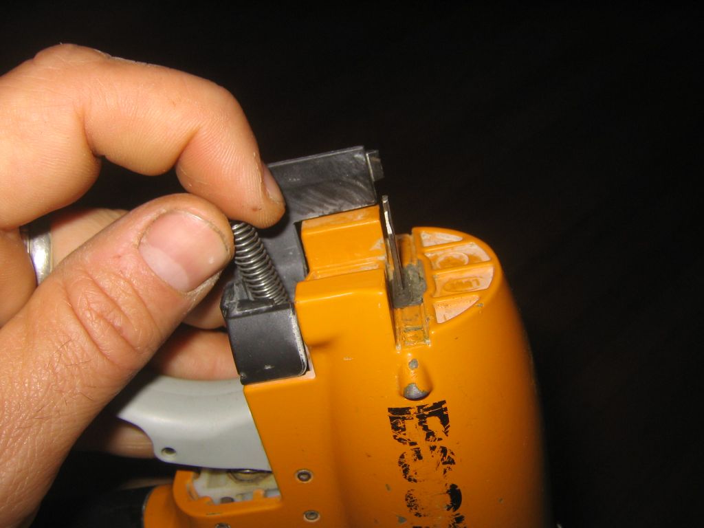
- turn body upside down, drop spring into hole near firing
pin (fig 8)
- place the rear of the nail cartridge assembly onto body
where the bolt connects the two
- thread the stainless steel upper trip carefully into its
slot behind the spring, and the firing pin into
firing pin slot (fig 9)
- replace upper two bolts on trip cover face
- replace bolt at rear of nail cartridge assy (fig 2)
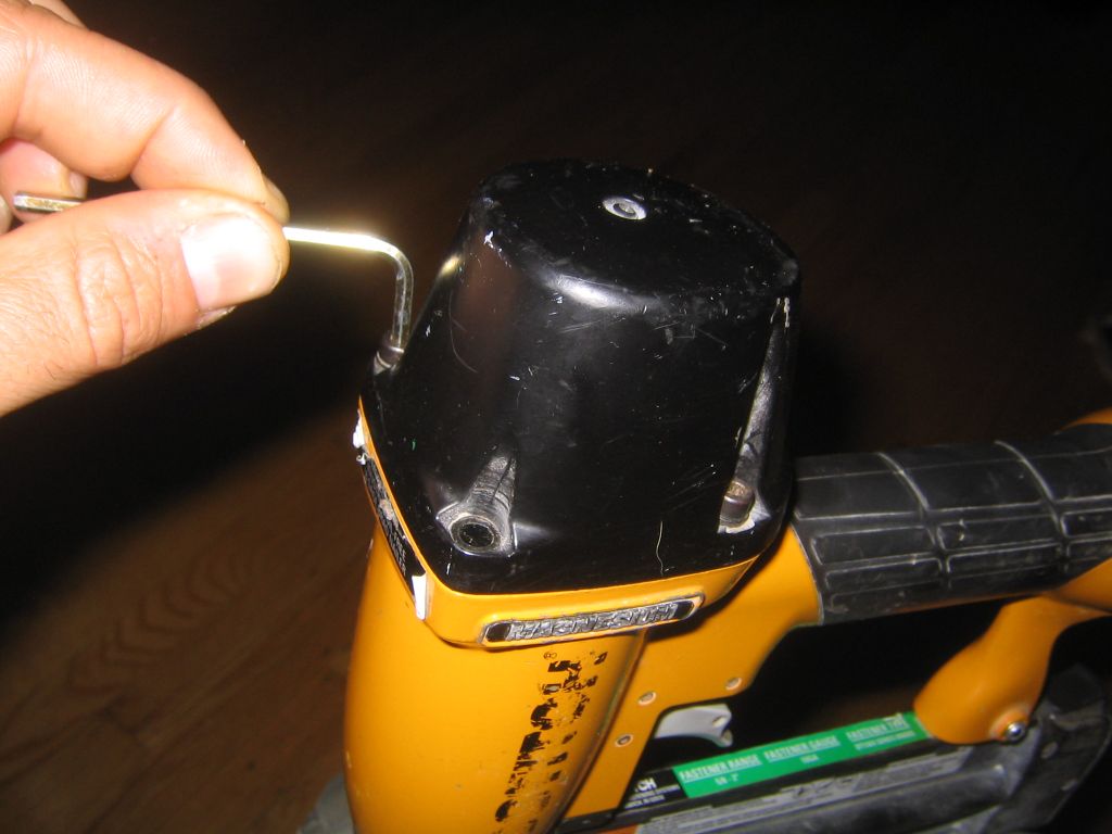
- remove 4 bolts around head (frame cap) (fig 10)
- carefully twist cap to open, catching spring and rubbery head
valve diaphragm
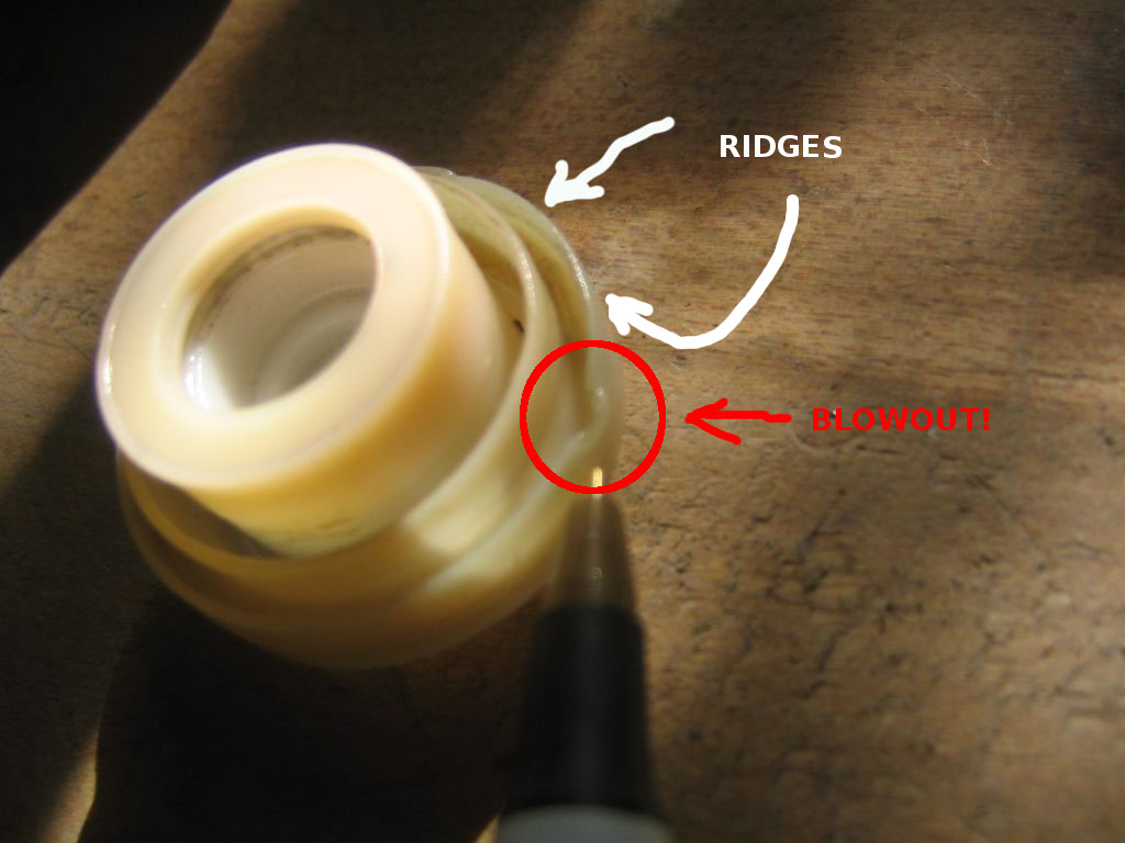
- first place head valve diaphram and spring onto plastic
sleeve in body (fig 11),
fitting the ridge on diaphragm into channel on sleeve
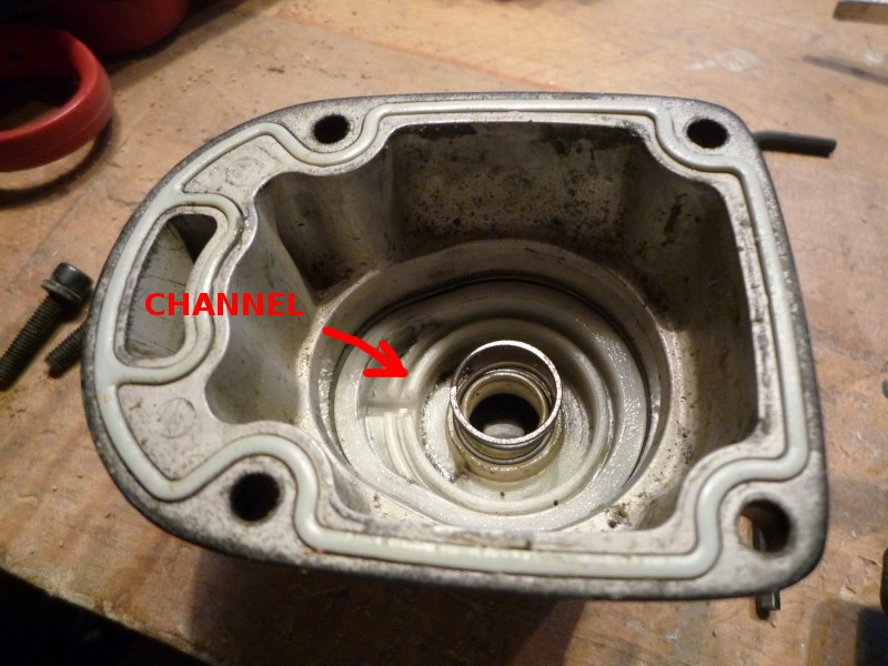
- look inside cap and find the other channel where the
upper ridge of the diaphragm fits into (fig 12); the trick will
now be to seat the diaphram correctly into this channel when the cap is placed
on the body.
- gently place cap onto body, twisting slightly to make sure
that the ridge on the diaphragm fits correctly onto the channel in the
cap.
- NOTE: if the diaphragm is not correctly placed (or if the gun is
operated at too high of a pressure), the ridge of the diaphragm will blow
out of the channels in the cap or the sleeve, and allow air to escape
around the trigger area instead of firing the pin. note the
blowout in this diaphragm: (fig 13). (even when the diaphragm
is apparently creased by blowouts such as these, it can still be
fit back into the channel and may eventually retain its shape; if not,
it will need to be replaced.)
- replace head bolts (fig 10)
replacing piston driver / firing pin
- disassemble frame cap (see above)
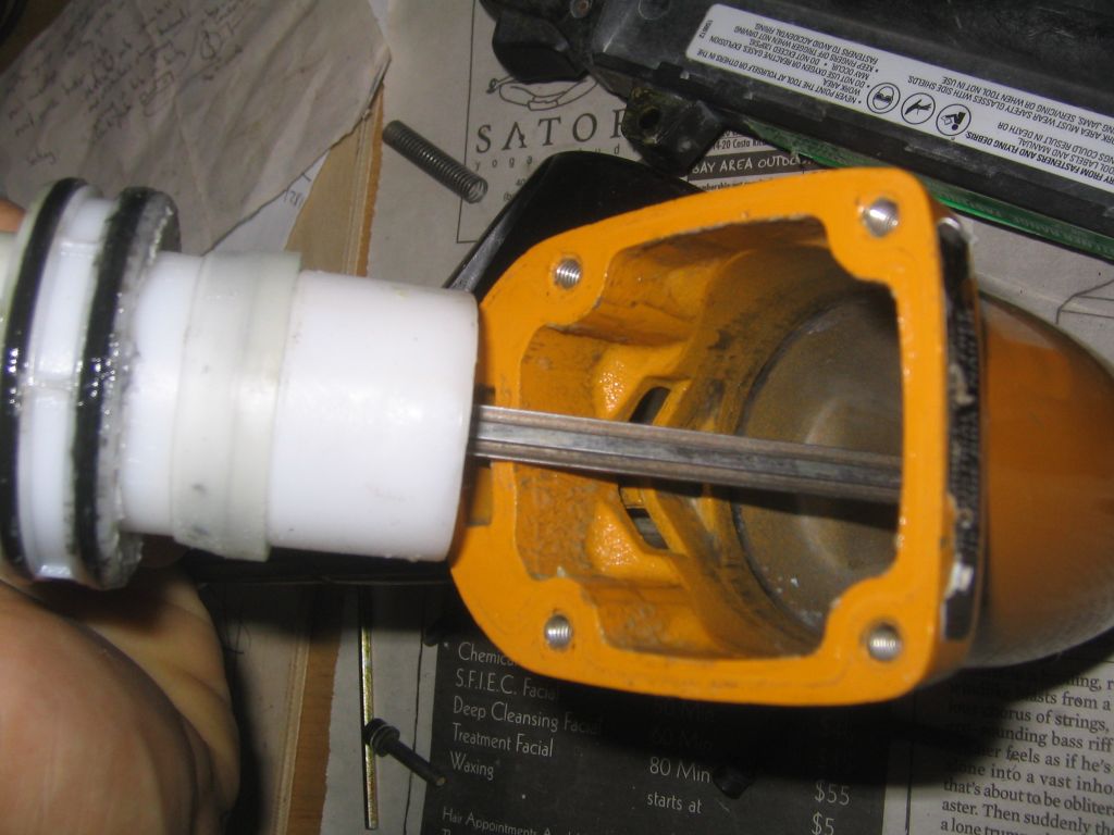
- pull plastic sleeve free of body (fig 14)
- pull piston driver / firing pin assembly out of plastic
sleeve
- replace with new piston driver / pin assembly
- orient the firing pin with the ridged side towards front of gun
[ridge can barely be seen in
(fig 14)]
- with firing pin extended most of the way out,
thread firing pin through slot in body
- press the sleeve/pin assembly back into place
- reassemble frame cap (see above)
|
|
fig 1
|
|
fig 3
|
|
fig 5
|
|
fig 7
|
|
fig 9
|

|
fig 11
|
|
fig 13
|
|
|
fig 2
|
|
fig 4
|
|
fig 6
|
|
fig 8
|
|
fig 10
|
|
fig 12
|
|
fig 14
|
|